3D Work Piece Compensation and Tool Vector Programming
Programming 5-axis machines is an effort that should not be underestimated. The rotary axes are often programmed directly with their angular position. The advantage of this is that the position of the machining head can be imagined when viewing the part program. The disadvantage, however, is that the part program depends on the kinematics of the machine and the part program cannot be transferred to another 5-axis machine without modification. To make the part program independent from the machine kinematics, you can use tool vector programming. By means of the vector’s components along the X, Y and Z axes, the direction of the tool is programmed. A prerequisite is that the CNC control must know the machine kinematics so that it can convert the programmed vectors into the real axis angles in real time.
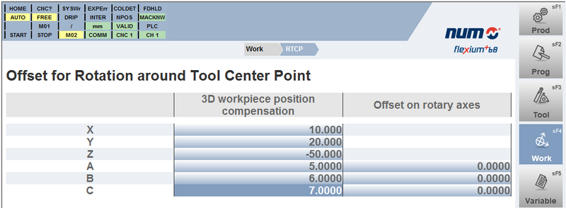
Under certain circumstances, the alignment of the work pieces to be processed on the machine can be very complex. In such cases, to increase productivity, instead of moving the work pieces, the CNC control offers the capability of compensating the positioning deviations (including angles) by means of corresponding correction values. The work piece remains misaligned, but the CNC knows such deviations and compensates them by software. For this purpose, the CNC control provides a special HMI page where the corresponding correction values can be entered. The coordinate system resulting from the shifts and rotations is called ‘Balanced Coordinate System’, or BCS.
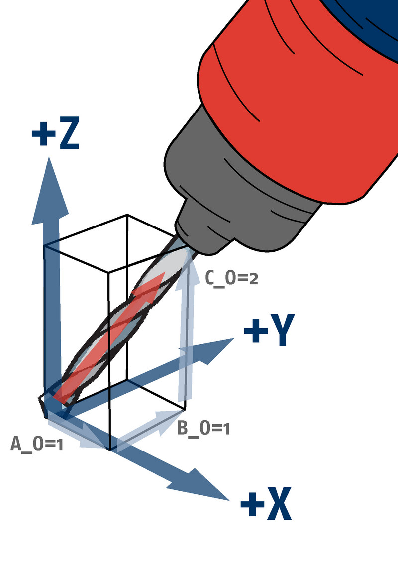
Now let us come to the tool vector programming. The basic CNC control mode implies programming the rotary axes’ angles. This standard mode can also be programmed with the G30 command. For tool vector programming, either G32 or G34 is used. If G32 is used, the tool vector is programmed with its projections on the main axes. The CNC control calculates the real axis positions in real time, taking into account the TCP (Tool Center Point) position, the tool dimension, any activated inclined plane and the corrections for BCS, as well as all other corrections and displacements. The programming is quite simple.
For example: G32 G1 X0 Y0 Z0 A_0=1 B_0=1 C_0=2 (see diagram).
Thereby the parameters A_0, B_0, C_0 define the tool vector. These parameters, as well as the axis positions, can of course be both numbers and variables. A normalization of the vector is not necessary. This is automatically done by the control.
The G34 command corresponds to G30, meaning that the axes’ angles are programmed, but G34 also takes into account the corrections needed both for the BCS and any activated inclined plane. With G34, the control calculates the tool vector from the entered rotary axis angles and then carries out the corrections as with G32. Programming G34 - the compensations needed for the BCS are considered but the shifts and rotations needed for eventual inclined plane machining have to be included in the part program, so the CNC control does not have to take care of them.
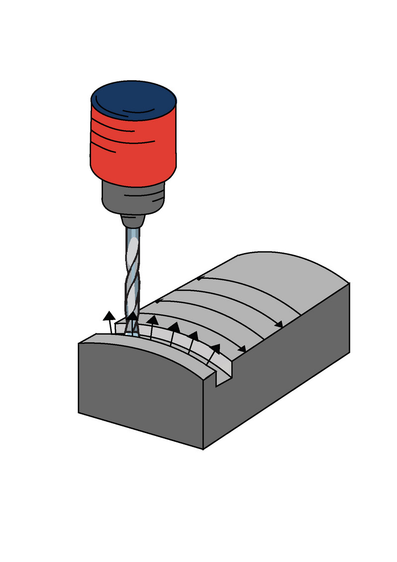
In the part program, the tool orientations are programmed block by block using the vectors or angles. On a 5-axis machine with simultaneous axes movements, the position and orientation of the tool vector normally changes in each NC block. To ensure that the machine now moves in accordance with the part program, the CNC control continuously interpolates the tool orientation synchronously with the path movement (see diagram). To ensure that the tool tip is spatially fixed during the rotary movements of the rotary axes, RTCP (Rotating Tool Center Point) must of course be active.
For more information on G32 and G34, or other aspects of 3D work piece compensation, please refer to the Flexium+ documentation or contact your NUM NTC representative, who will be happy to provide suggestions and solutions.


